High Power Zone Shear (no existing standard)

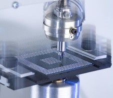
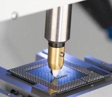
This is an alternative (optional) method to high speed shear testing. It involves shearing many solder balls in one pass of the shear tool. One or more rows can be sheared simultaneously.
Zone shear is done at much lower speeds that those typically used in high speed testing and the test is best caried out on the 4000 machine. You will however need a high power XY stage and a 100kg load cell.
If you are only doing zone shear it is most sensible to upgrade or buy a suitable modified 4000 machine, rather than buy a 4000HS.
The only advantage of zone shear is increased throughput, although even this is questionable due to the method of analysis. This is qualitative rather than quantitative and consists in assessing the failure mode of each bond for the remaining area of solder. During the test one or more balls are driven into the next one and therefore successive bonds are subjected to different load conditions. This means that there is no measurement of bond strength. Furthermore, assessment of the failure mode is subjective, involving the averaging of area evaluations across tens of bonds.
High Speed Cold Bump Pull (JEDEC standard pending - early 2007)
Pull testing at high speed also requires a different set up from conventional pull testing. As the clamping jaws must have contact with the ball, an acceleration distance between the jaw and the sample is not possible.
This is overcome by the use of a pneumatically controlled "rising" table which accelerates the sample to the test speed setting.
In a similar way to high speed shear, failure mode analysis is more important than measurement of the bond strength.
To assist you in this, DAGE provides extensive analysis options. These are force versus displacement/time (FvD or FvT) curves and calculation of energy values. In order to understand these, consider the following example of high speed shear tests for two types of failure. For each shear event a FvD graph is plotted representing the forces recorded as the shear tool passes through the bond. Notice that the shapes of these curves are fundamentally different for the two types of bond failures. Not only can you see that the failure modes are different from just the shapes of the graphs, but comparison of the energy values calculated by software confirm this.
In the example shown, note the force displacement curves for two types of bond failure a classic brittle fracture and a solder failure. Observe that curve shapes are radically different. In both tests, the force rises rapidly to the peak, but with brittle fracture (Test 1) it descends equally rapidly as the bond breaks catastrophically. Contrast that with Test 2 where there is ductile failure of the solder ball.
Energies are represented by the area under the force-displacement profiles, so it is immediately apparent that the total energy values for the two failure modes are starkly different. Total energy for the brittle fracture in this instance is around 0.4mJ compared with nearly 2mJ for the solder failure. Not only does the software calculate the total energy, but there is an option to see a separation into the energies associated with initial ball distortion and actual bond breakage. On the graph the vertical dashed line divides the energy to peak force from that following.
In order to give you confidence that the test is taking place at the chosen speed, the system has an option to display a velocity trace for each test.
Applications:
High Speed Shear (JEDEC standard published October 2006)
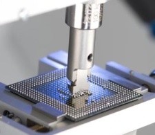
The high speed test regime requires an area in which the tool can accelerate before contacting the ball. Therefore the device has to be cleared of all other balls, except for the single row being tested (in effect 2 rows, at right angles to one another on a device such as a BGA). The distance (retraction) required to accelerate the sample to the test velocity is calculated automatically, and will vary according to the value chosen
As explained above, the emphasis in high speed bondtesting is on assessment of failure mode rather than measurement of failure force.
HIGH SPEED BONDTESTER


High Speed Bondtesting

Solder ball joint integrity has always been an important issue in device manufacture, but never more so than with the introduction of lead-free solder. Although lead-free joints can be stronger, it has been noticed that they are particularly susceptible to brittle fractures at the component interface (intermetallic region) and pad-cratering at the board interface. Such failures can occur over the full life cycle of a joint, from manufacturing through testing to end use of the product itself. As the incidence of such failures has increased with the introduction of lead-free materials, the industry has acknowledged an urgent need for improved testing techniques. However, interest in brittle fracture and pad-cratering is not limited to lead-free; many solder alloys and pad surface finishes can be equally problematic.

How does the new high speed bondtester address these concerns?
When shear testing at traditional speeds (less than 20mm/sec), the dominant failure mode tends to be solder ball shear, i.e. a break within the solder material itself. When this happens, the only conclusion to be drawn from the data is that the bond strength is greater than that of the sheared solder ball. This makes it virtually impossible to compare the effects on bond strength of different pad finishes, pad constructions and solder alloys. Extensive research has now proved that testing at much higher speeds (typically above 1000mm/sec if testing for potential brittle fractures) will produce many more bond failures, thus allowing the performance of different components and constructions to be compared. A similar situation exists when pull testing (CBP) solder balls.
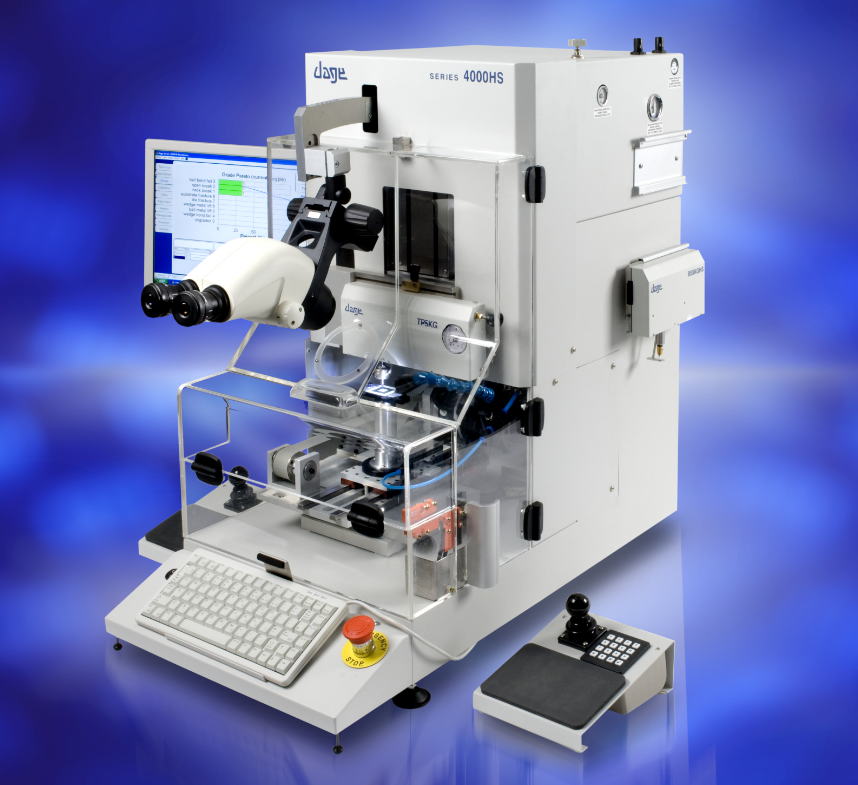
The new machine is based on the DAGE-4000, but there are significant differences to the mode of operation for both shear and pull modes with speeds up to 4m/sec for shear and 1.3m/s for pull. Other differences are advanced analysis options; specifically force versus displacement graphs and energy measurements. These are in addition to the conventional peak force measurement.
Most importantly, the emphasis in test evaluation has moved away from precise measurement of failure force values to assessment of failure modes and energy measurements. As mentioned above and described in more detail below, the 4000HS contains new features to facilitate failure mode analysis. These are illustrated in the example shown below in the Application section High Speed Shear.
Suitable for:
  • Impact testing applications (as an alternative to 3 and 4 point bend testing and drop testing)
  • Brittle fracture joint failure analysis
  • Lead free solder ball joint evaluaton
  • Shear testing multiple ballbond simultaneously


Isodynamique Group of Company (All rights reserved)


4000 HS